


Introduction
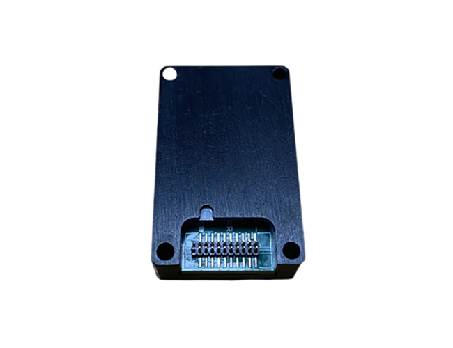
TDMG-106C MEMS inertial measurement unit is a product developed for the demand represented by vehicle navigation. The system uses multiple redundant MEMS inertial sensors, which can timely diagnose and process IMU faults and provide support for automotive functional safety. The TDMG-106C MEMS IMU is mainly composed of a three-axis silicon micro-MEMS gyroscope, a three-axis silicon micro-MEMS accelerometer, an information processing circuit, a system navigation software, a system structure component, a system test cable and a system test software. Its heading axis selects high accuracy gyroscope to aim at the characteristics of passenger cars, which can ensure that the product maintains a high heading accuracy, so as to realize long endurance and high precision dead reckoning with the assistance odometer under the condition of satellite lost.
Aim at passenger car navigation scenarios, the TDMG-106C is integrated with multiple redundant inertial sensors, which can realize the fault diagnosis and timely alarm of product output. For simple failures (such as single sensor failure), the fault can be isolated and the operation can continue.
By default, the following outputs are provided: 3D angular velocity, 3D acceleration, and gyro temperature. The chips inside the system are selected car grade devices.
Features
● Vehicle grade devices
● High precision Z axis gyro
● Multi-sensor redundancy and fault-tolerant design
● Volume, low weight, low power consumption
● -40℃ to +80℃ full temperature calibration compensation
● 1KHz high-speed sampling
● Resistant to harsh mechanical environment
● With software online upgrade function
● Sensor self-diagnosis
● Software online upgrade function
Application
● Vehicle navigation
● Mobile mapping
● Guidance control
● Vehicle and ship attitude measurement
● AGV car
● Port automation
● Unmanned aerial vehicle
● Unmanned vehicle
● Unmanned ship
Specification
|
ITEMS |
TDMG-106C |
|
|
Gyroscope |
Measurement range(°/s) |
±500(X,Y),±200(Z), |
|
Bias(°/s) |
≤0.1(X,Y),≤0.003(Z) |
|
|
Bias stability(°/h,10s smooth) |
≤10(X,Y),≤0.5(Z) |
|
|
Bias instability(°/h,Allan) |
≤4(X,Y),≤0.1(Z) |
|
|
Bandwidth(Hz,adjustable) |
50 |
|
|
Accelerometer |
Measurement range(g) |
±16 |
|
Bias(mg,full temperature) |
≤5 |
|
|
Bias stability(mg,10s smooth) |
≤100 |
|
|
Bias instability(mg,Allan) |
≤30 |
|
|
Bandwidth(Hz,adjustable) |
200 |
|
|
Electrical/Mechanical interface |
||
|
Power supply(V) |
3.3±0.1 |
|
|
Power consumption(W) |
<1 |
|
|
Communication port |
1 LVTTL port, 1 synch input, 1 synch output |
|
|
Updating rate(Hz) |
200 |
|
|
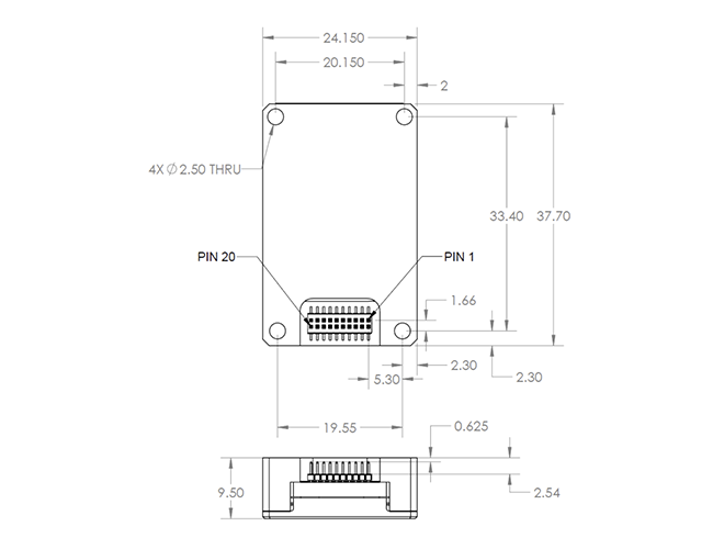
Size(mm×mm×mm) |
37.70×24.15×9.50 |
|
|
Weight(g) |
31.5±3 |
|
|
Environmental condition |
||
|
Working temperature(℃) |
-40~80 |
|
|
Storage temperature(℃) |
-55~85 |
|
PIN definition
|
PIN No. |
Definition |
Note |
|
1 |
IMU data synch output impulse |
Only LVTTL signal, falling edge efficiency |
|
2 |
Synchronous signal input |
LVTTL signal |
|
3 |
SPI Clock/ UART TX |
SPI/UART multiplex |
|
4 |
SPI Data Output /UART RX |
SPI/UART multiplex |
|
5 |
SPI Data Input |
|
|
6 |
SPI Chip Select |
|
|
7 |
Data Ready(SPI Ready)/SPI-UART Port Select |
If short connected with GND, PIN 3 & 4 will be UART. |
|
8 |
Enternal Reset |
|
|
9 |
Standby |
|
|
10 |
Power supply + |
3.3V±0.1V |
|
11 |
Power supply + |
3.3V±0.1V |
|
12 |
Power supply + |
3.3V±0.1V |
|
13 |
Power/Communication GND |
Ground |
|
14 |
Power/Communication GND |
Ground |
|
15 |
Power/Communication GND |
Ground |
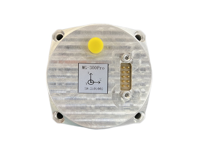
Introduction TDMS-300Pro MEMS Integrated navigation system is a highly reliable and cost-effective six-axis MEMS inertial...
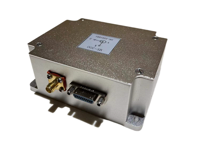
Introduction TDMS-300 MEMS integrated navigation system is a highly reliable and cost-effective six-axis MEMS inertial/sa...
Introduction TDMS-200 high accuracy integrated navigation and positioning unit is a real-time navigation and positioning ...


Thank you for your message and we will contact you within 24 Hours of your submission to resolve your issue
 Online consultation